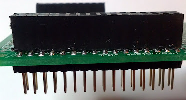

In an earlier post, I mentioned that Loki has a novel way of avoiding the pin conflict issues that plague other stackable expansion board systems. Today we’ll take a closer look at just how that works.

Most stackable expansion systems, such as Arduino, use long-tail thru-hole headers, that connect directly from the receptacles on the top of the board through to the pins on the bottom. These are convenient - though surprisingly hard to come by - and straightforward, but have a major issue: stacked boards must avoid using the same pins as each other, or they’ll be incompatible. Worse, there’s no good way for a shield designer to pick pins that won’t conflict, other than picking specific other shields to ensure compatibility with. Every user has to check carefully before purchasing a shield to ensure it won’t conflict with the other ones they want to use. Aside from being a hassle, this limits opportunities, making otherwise well suited expansions unusable.
There must be a better way, right? Fortunately, there is, and Loki implements it. Here’s how it works: Instead of using thru-hole stacking headers, Loki uses surface mount headers on the bottom, and surface mount receptacles on the top. Common signals such as power, ground, and the I2C bus are passed straight through, bottom to top. IO pins, however, are handled somewhat differently.
Instead of using any pins, each plank uses the first few pins from the GPIO bank. Then, it routes the remaining pins on the bottom header to the top, shifting them up to fill the ‘gaps’ left by the pins it consumed. So if a plank needs 4 pins, it will use pins 1-4 for itself, then connect the incoming pin number 5 to outgoing pin 1, 6 to 2, 7 to 3, and so forth. In this fashion, because used pins are never passed through, every pin can only ever be used by a single plank, and thus no plank has to worry about conflicts. You can keep stacking additional planks until you run out of IO pins!
Of course, the reality is slightly more complicated than the theory, but only a little. A plank that needs to use a lot of IO pins could have some difficulty cleanly routing the remaining pins to the first headers on the top side, so Loki splits the pins into two independent banks, consisting of the first half and the last half of the pins. A plank must take an equal number of pins from each bank. This simplifies the routing somewhat, while still preserving the flexibility. It’s also possible - though uncommon - for a plank to take pins other than the first ones in a bank. This limits where in the stack the plank can practically be placed, but still works fine: the plank just ‘shifts up’ the remaining pins to fill the gaps.
Here’s an example header layout for a plank that uses one pin from each bank:
As you have no doubt noticed from the photos, Loki has two expansion headers. The one on the top, a 2x16 header, contains all 32 GPIO pins, and uses the scheme described above. The one on the bottom, a 1x10 header, carries the power rails, ground, reset, the hardwired I2C bus, and a few other control signals we’ll go into later.
If you’re curious to learn more, or start planning out your own expansion planks, a preliminary specification for planks is available here. Beware that it may change before 1.0 - so if you are intending to make a board, get in touch first!
Some of you may be thinking that this system, ingenious though it may be, could lead to some confusion regarding which microcontroller pins are assigned to which plank pins, and you’d be right. Loki has a clever solution to that conundrum too - the details of which will be revealed in a future blog post.