Labs update

Ordered the parts for the Re:load kits today. Mostly from Farnell. I have a few parts to order from Future Electronics, but I’m having trouble trying to invoke their free shipping option. Definitely the biggest single electronics order I’ve ever placed.

My reflow oven arrived today. I posted a review of it on the Dangerous Prototypes forum here. I’m very happy with it, though I wish even more now that I had a solder paste dispenser.

I spent some time working on another unreleased project. Hopefully this one will see the light of day shortly - keep an eye out.

Over the weekend, I plan to test out the Loki motor and sound planks, finally, and write up some getting started documentation for the Loki Alpha testers. I also plan to write up the kit instructions for the Re:load.

Comment

Introducing the Loki Shield Plank

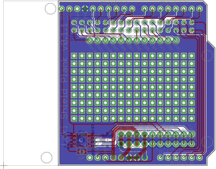
Time to introduce another Loki plank! This one’s a direct result of a suggestion from a (future) user: the Shield Plank.

The Shield Plank, as its name implies, provides an interface from the Loki expansion system to the Arduino one. On the bottom are standard Loki connectors; on the top are Arduino compatible stacking headers. Conveniently, the Arduino and Loki headers differ enough in their header spacing that it’s possible to use thru-hole headers for both sets.

The board itself is, naturally, pretty straightforward. 20 of the Loki’s 32 pins are broken out and routed to Arduino’s D0-D13 and A0-A5. The remaining 12 pins are routed to headers adjacent to a prototyping area for added convenience. Of course, some or all of those pins may be unavailable due to other planks below it, but it’s worthwhile to break them out anyway.

The Arduino R3’s I2C headers are connected to the Loki’s configuration I2C bus. The relevant power lines are connected between the Arduino and the Loki too, naturally. The only pin not connected is the AREF pin; fortunately this is infrequently used on Arduino shields.

Naturally, this plank will only work with 3.3 volt compatible Arduino shields. Fortunately, with the release of the Arduino Due, and other 3.3 volt Arduino variants, these are growing more and more common. I’m optimistic that this will open up the Loki system to a wide variety of existing expansion boards designed for the Arduino system.

Comment

Review: SixtyFourPixels LoFi Gamer Kit

Recently, on Tindie’s first seller’s hangout, I purchased a kit I’d had my eye on: The SixtyFourPixels LoFi Gamer Kit by Tindie seller Hotchk155. It bills itself as “based around an 8x8 LED matrix which can display in glorious red/green and orange! Sound is provided by a piezo beeper for a truly retro, minimalist gaming experience”, and it looked like it would be fun to build and play with.

Postage and packaging

The kit arrived very promptly in the mail, neatly packed in a small shipping box. Inside was a lovely little black giftbox with a nicely printed sticker on top:

SixtyFourPixels Box

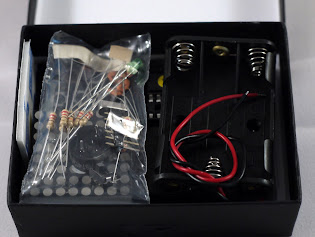
Peeling off the stickers holding it shut (which sadly requries damaging the box a little) revealed a well organized and tidily packed kit.
SixtyFourPixels Kit in box

Unpacking reveals all the parts included:

SixtyFourPixels Kit Contents

All the DIPs and the display are carefully inserted in a piece of high density foam for safe shipping; the other parts come in a ringgrip bag. Also included is a small and well laid out sheet with a parts list (more of which later) the URL to a full guide, and an annotated color photo of the box contents, printed on nice thick paper and neatly folded.

Assembly

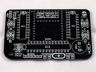
The PCB appears to be well made and carefully laid out. Here it is in more detail:
SixtyFourPixels PCB

Note that despite the instructions, Hotchk155 clearly recognizes that makers will often decide to skip straight to the “making it” bit, hence the very clear and well-conceived warning “Solder resistors to back of board before adding LED matrix”. I have no doubt this will save a few hasty makers a lot of trouble.

Assembly is quite straightforward for anyone with kit building experience. For most footprints there is only one sensible choice of part. There are two exceptions to this rule: two values of resistor, but there is eight of one value and one of the other, so it’s clear which is which. More apt to confuse are the two distinct values of ceramic capacitor in the same packaging. Here, the instruction sheet helpfully specifies “(C1, C2) 33pF ceramic capacitor (33 code)” and “(C3, C4, C5, C6) 100nF cap (104 code)”, removing any ambiguity as to which goes where.

The BoM consistently contains these helpful tidbits, and they make building the kit considerably more straightforward. For instance, regarding the LED matrix display, it says “Pin 1 is indicated with a colored label”; regarding LED1 it states “The longer leg is the anode (+ terminal)”. It’s clear that Hotchk155 has taken the time to think carefully about who will make this kit and what mistakes they may make, as well as going through the process himself. The only thing I would add for those of us who tend to disdain instructions is to fit the LED matrix before the IC sockets; I did it the other way around and spent a frustrating couple of minutes trying to line the pins up.

For those of you who prefer the step by step approach the instructions are clear and detailed - and sure enough, they tell you to put the LED matrix on before the IC sockets.

When it comes to soldering the kit, the experience is generally pleasant and pain free. There are a few parts with rather small annular rings, making soldering a bit trickier for the inexperienced; other than that it’s a very simple kit to assemble. Someone with intermediate experience could certainly do it; I expect a beginner would do fine if they were being tutored. Assembly took me about half an hour.

Here’s the kit, fully assembled:

SixtyFourPixels Assembled

The only criticism I can level at this point is that it doesn’t come with batteries (I didn’t expect them, but it would be nice); I was forced to put the kit aside until after work, when I came home with batteries. Probably a good thing, or I would have arrived at work even later than I did.

Using It

After turning on, SixtyFourPixels shows a symbol representing a game; the first one in the list is fairly clearly space invaders. Pressing B and D scrolls between menu items; pressing C chooses one. This pattern is repeated inside games, too - the lower two buttons are generally for movement, and the upper two are for actions.

Pressing C on Space Invaders dumps you into an extremely minimalist but nevertheless recognizable space invaders clone. Ships - yours and theirs - are single pixels, as are your defenses and both of your bullets. The device’s versatile 3 color support helps distinguish things from one another. When you lose - as you inevitably will, your score, followed by the high score, scroll past the screen in oversize numerals.

The other games that come with the kit are a breakout clone, connect-4, and simon. They’re all instantly recognizable, surprisingly fun to play, and in some cases quite challenging. Space Invaders was tough, and in my brief attempt at playing Connect 4, the computer trounced me three times in a row, with embarrasing ease.

All of the controls were figured out with trial and error, incidentally - and not a great deal of error. They’re as intuitive as they can be given the limitations of the device.

The SixtyFourPixels is based on an ATMega328, the same device used by the Arduino Uno and most clones. It runs the bootloader, and the board comes with a header for connecting an FTDI serial attachment, meaning you can reprogram it yourself. The Wiki even has instructions on writing your own games.

Conclusion

This is an exceptionally well thought out, tidily presented, and excellently executed kit. It’s easy and fun to assemble, and has a novel concept that it takes good advantage of. Documentation is first-class. The built in games are a blast, and do a good job of showing just how fun a minimalist experience can be. I greatly look forward to future games, both first- and third- party.

I think this would be an excellent kit for teaching kids soldering and programming; it’s also good fun for anyone who likes to build kits, play with microcontrollers, or if you just want something novel. I daresay it would make a decent development board for a few non-game purposes too, potentially.

Highly recommended. Go and buy one!

Comment

Labs Update

The weekend was spent in various Loki and Arachnid Labs related activities. The most boring (but necessary) of these was finding and setting up an accounting package of some sort to keep track of where all the money comes from and goes to (mostly goes to, so far).

I redesigned the layout of the EEPROMs onboad each Loki plank to use a lot less space, opening up the possibility of switching from discrete EEPROMs and XOR gates to an integrated solution such as an ATTiny45 MCU. This won’t be any cheaper - it may, in fact, be marginally more expensive - but it will make every plank’s BoM one part shorter, and reduce layout size. The programmer tool has been updated to read and write the new EEPROM format.

One change in the new format is that instead of using (long) GUIDs to indicate a plank’s identity, I’ve switched to a system similar to USB, with “Maker IDs” and “Plank IDs” of two bytes each. This requies centralized allocation of IDs, but unlike USB-IF, I don’t intend to charge people for the privelige; they’ll be available if and when needed. I’ll probably also allocate a generic Maker ID for anyone who doesn’t want to register for their own for whatever reason.

Currently, these IDs serve two purposes. The most significant is that they’ll allow a future version of the Loki bootloader to identify what planks are attached and compare that to the ones that were attached when the program was bootloaded. A user configurable option will be provided to enable the board to refuse to boot if the configuration does not match. Sophisticated programs may also choose to use the IDs in a similar way to USB, allowing them to be reconfigured by plugging in new boards.

The second purpose is for convenience; a URL can be generated from the maker ID and plank ID to an as-yet-unwritten registry, which will redirect to the plank creator’s page, with documentation.

I also finished converting the plank specification from a Google Doc to a page; it can be found here, and that URL will be its new home from now on; the google doc will be obsoleted. I’ve updated that document with details of the EEPROM layout. I’m still working on the Loki reference manual.

Some time over the weekend was spent dealing with Re:load logistics. I’ve ordered the usuall dull items like postage bags and labels, as well as a couple of other shinier things I have planned. Since the number preordered is so much higher than I expected, I’ve been looking at other suppliers and asking for quotes. One surprise was that Farnell no longer have enough of the larger heatsink in stock to satisfy my preorders; the good news is that I found an alternate supplier who has a compatible heatsink with even better thermal performance (2.6C/W vs the current 3.3C/W), so all Epic Re:load purchasers will now be getting a free upgrade to an improved heatsink. I also ordered a truly excessive 1000 packets of thermal paste from a supplier in China. I chose express shipping; hopefully the Chinese New Year won’t delay them too much.

On Sunday I took the plunge an ordered an SMD reflow oven off EBay; it’ll be arriving some time this week. Even though the Re:load has only one SMD part to solder before sending out the kit, this still ought to speed things up a bit.

Last but not least I sent the updated Loki board off to Hackvana for fabrication, along with a couple of new prototype plank designs: the constant current LED plank you’ve already seen, and a new one that’s yet to be announced.

Comment

Importing polygons into Eagle

Surprisingly often, I find myself wanting to import vector images into eagle, and have them appear as polygons - usually for silkscreen. Whilst importing vectors as lines is practical - although ridiculously awkward - up until now I haven’t found a single practical way to import a vector drawing as polygons.

That changed recently when I stumbled across Cruz Monrreal II’s svg2poly. svg2poly is an Eagle ULP that, within the scope of its limitations, does a very good job of importing vector shapes into Eagle. Getting it working was a revelation - I no longer have to mess with awful bitmap imports that arrive as a huge series of tiny rectangles, or spend hours tracing things.

Read more

Improvements to the re:load

The response to the Re:load has been nothing short of astonishing. 60 orders on Tindie in less than 24 hours! I’m really looking forward to getting them out to people, and to seeing what they do with them.

I’ve spent the evening tweaking the PCB a bit for the production run. No major changes, but I’ve swapped parts around a bit to move the potentiometer further away from the heatsink. I also reversed the potentiometer - it’s currently configured the opposite to the conventional way, so counterclockwise is up and clockwise is down. That’ll be fixed in the production units.

I’ve also come across some spring terminals that I think will make a much better choice than the screw terminals the Re:load currently has. They’re the same pin spacing, but they’re deeper, so I had to shuffle things around a bit to accommodate them. Here’s what they look like:

(Only, imagine one with only two poles!)

I’ve been hearing a lot from people over the last 24 hours about what they want to do with their Re:load. Lots of really creative stuff: people want to use them to regulate LED strings, hack them for digital control by removing the potentiometer and feeding the opamp straight from a DAC or PWM, rig one up with their own heatsink, even create multi-channel test loads with several of them. I’m really looking forward to seeing what people make with their Re:loads, and I hope people will send in photos and descriptions when they do.

Comment

Introducing re:load

A while ago I found myself in need of a dummy load for testing a power supply, and was surprised to find that there weren’t any good kits around for this. On the commercial end of things, dummy loads tend to be large, powerful, and incredibly expensive. There’s a few hobbyist projects out there, but they tend to fall into two categories: absurdly overcomplicated and expensive, or unavailable. So I set out to design and build my own, hopefully solving the problem for everyone.

Re:load is an adjustable constant-current load with several key properties:

  • Cheap. $15 for the 0-3A version!
  • Self-powered. A general purpose dummy load shouldn’t need external power, and Re:load doesn’t.
  • Versatile. Operates over 3.3 to 30V, and at 0-3A for the regular version or 0-6A for the ‘epic’ version. Handle up to 12W continuous (regular) or 20W continuous (epic), or more with your own jumbo heatsink.
  • Virtually indestructable. As long as you don’t exceed 30V, there’s not much you can do to damage this. ESD, overcurrent, overtemperature and reverse polarity are all protected against.
  • Small. Chuck it in your toolbox once you’re done and pull it out when you need it next.

Most DIY adjustable loads use regular FETs or BJTs as the main pass elements, but this made me nervous. These devices don’t have any overtemperature protection built in, so they’ll happily self-destruct if you put too much power through them. For me that just seemed like a matter of time. After a lot of searching, I found the BTS117 and BTS141 “Smart low side switch” ICs. These remarkable little devices have built in ESD, overcurrent, overvoltage, and overtemperature protection, making them ideally suited for a dummy load. They act just like regular FETs, too, making them easy to interface with.

The basic circuit for building a constant current load is pretty straightforward.

The FET is drain is connected to the positive rail, and its source is connected to one end of a shunt resistor. The other end of the shunt resistor goes to the ground rail. This forms the main current path for the dummy load. The FET’s gate is connected to the output of an opamp, and the negative input of the opamp is connected to the junction between the FET source and the shunt resistor. This forms a feedback loop: the opamp will adjust the voltage on the FET’s gate to ensure the voltage across the sense resistor is the same as the voltage on its positive terminal. Since the voltage across the sense resistor is proportional to the current flowing through it (and thus the FET), the result is a constant current load. Presto!

In order to be able to adjust the current, we connect the opamp’s positive terminal to a voltage divider made of a potentiometer and a fixed resistor. Selecting the value of these correctly allows us to vary the load current over the desired range linearly as we turn the potentiometer.

A regulated supply is necessary for all this to work, of course, and I’ve gone with the LP2950. This little 3-terminal regulator supplies up to 100mA - way more than we need for our opamp and voltage divider - with remarkably good regulation.

The choice of opamp is quite important here. We need something that can handle input voltages near the ground rail, provide output voltages near the positive rail, and have low offset voltage for accurate operation. After a bit of searching, the MCP6002 turns out to be a good choice. Its input offset voltage is 4.5mV - equivalent to about 100mA of current across the dummy load in our configuration. It can handle input voltages right down to the negative rail, and produces output voltages within 25 millivolts of the positive rail. It’s also affordable, making it perfect for our application.

Since the IC has two opamps in it, we may as well put the other to use. A couple of resistors allows us to provide a test point for checking the load current with your multimeter in voltage mode - 1 amp corresponds to 0.1 volts.

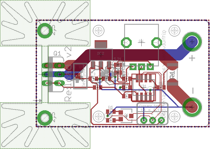
Laying out the PCB was an interesting task. After working with SMD parts for so long, thru-hole parts seem huge. I came up with a design I’m quite happy with on a 3cm x 5cm footprint:

The heatsink is a standard footprint that can be soldered directly onto the PCB. Variants are available in different sizes and thermal capacities, too.

After the PCBs arrived, testing and qualifying it was a fun exercise. As I’d hoped, despite my best efforts I’m unable to destroy it. The thermal shutdown cuts in smoothly when it goes overtemperature; reverse polarity draws a lot of current from the power supply through the FET’s body diode but otherwise does no damage.

After a dab of thermal paste, the heatsinks perform rather well too. The smaller one handles 12W continuous, while the larger one can handle 20W of power dissipation.

So what would you do with a re:load? You could use it as I am - to test a power supply. Hook it up to a constant voltage supply to turn it into a constant current supply for electroplating, to test out a high power LED, or for other purposes. Or hook it up in winter for a bit of extra heat.

If you’re interested in a re:load to call your own, they’re available as kits on Tindie.

Naturally, the whole project is OSHW. Get the complete schematics to build your own here.

Comment

Constant Current Plank

As mentioned in a previous progress update post, I’ve been working with Firehopper, from the #sparkfun channel on freenode, to design a constant current plank, aimed at driving high powered LEDs. It’s just about done, with only some minor silkscreen issues to go.

The board makes use of two STCS2A constant current driver ICs from ST Micro, in PowerSO form (an SOIC outline with a thermal pad on the bottom). Each is capable of controlling up to 2A at up to 40V. They support PWM - which is hooked up to Loki GPIO pins, naturally - a fault indicator for when there is no load present, and their maximum current is configurable via a shunt resistor.

The use of a shunt is actually somewhat inconvenient, since it makes adjusting the current limit awkward. There aren’t a great number of 0.1 ohm potentiometers that can handle 2A out there. Instead, we’ve gone with a slightly more complex solution, involving an opamp. A potentiometer in a voltage divider configuration provides a reference voltage; one opamp per channel attempts to make the shunt voltage equal to that, by feedback through the controller’s sense pin. This will make it easy to tweak the current limit at runtime with a single potentiometer. PWM still makes it possible to individually dim each channel from the MCU, of course.

The provision of a PWM pin makes this board a perfect fit for the PSoC’s built in lighting controller module, the PrISM. Instead of using PWM like regular controllers, PrISM uses a random sequence generator hooked up to a comparator. Each step, the value in the comparator is compared to a generated value, and the output goes high if it’s higher, and low otherwise. The result is much like PWM, but with the significant advantage that you can update the compare value at any time without glitches, and the effective illumination will quickly and smoothly adjust to the new value.

I’m quite pleased with the layout on this board, too. I’ve been trying pay more attention to the attractiveness of PCB layouts recently, after seeing some really nice ones in #hackvana on freenode. A symmetrical and well laid out PCB looks a lot more attractive than one with parts all over the place, and I think I’ve done a pretty good job here.

Comment

The Loki Motor Plank

Last of the initial set of Loki planks - but certainly not least - I present the Loki Motor Plank:

The Motor Plank is a straightforward DC motor driver utilizing the TB6612FNG dual H-Bridge motor driver. It’s capable of driving two DC motors at up to 1.2A each - or you can parallel it to drive a single motor at a higher current.

The board uses six GPIO pins, for the A, B and PWM inputs on each H-Bridge. The board features screw terminals for the motors and optional DC power in, and bicolor LEDs to indicate motor speed and direction. An optional jumper allows you to connect the motor driver’s power rail to the Loki’s VIN terminal. This gives you the flexibility of powering the motors straight from the Loki if using a DC adaptor and low power motors, powering the Loki from the motor driver screw terminals, or of having two entirely separate supplies for motor and Loki.

The plank’s naturally pretty straightforward to operate: simply set the A and B inputs for the desired direction of motion on each motor, and PWM the PWM pins to control motor speed.

Of course, the Loki’s flexibility when it comes to GPIO and peripherals makes it easy to implement motor driving schemes other than Sign-Magnitude; I look forward to seeing someone implement Locked Anti-Phase Drive with no CPU overhead!

Comment

Daily progress report

I spent this evening polishing off the library code for the component to drive the Nokia display, and porting the Game of Life demo to it. Users will now have a nice convenient packaged library for using the display, with no knowledge of its wire protocol required. Data is transferred to the screen using DMA, so you can update the whole screen with no involvement at all from the CPU, making it a very efficient process. I still need to write up some documentation for the library and the Game of Life project. I’d also like to enhance the library component to add at least basic text support, so people don’t have to cook up their own solution.

I’ve also moved the official Loki source repository to the Arachnid Labs github account; you can find it here. All the schematics for the Loki and the expansion boards, the demo code, dimensional drawings, the bootloader host code, and so forth can be found there. The only component that is not yet in the repository is the bootloader code; it will be added shortly. Everything I can make OSS in this project, I will make - no ‘secret sauce’ held back!

Finally, I’ve started working with Firehopper, a denizen of the #sparkfun IRC channel on freenode, to design another Loki expansion plank. This one’s a constant current driver plank, capable of driving up to 2A on two separate channels and PWM dimmable, designed for high power LEDs. Keep an eye out for an intro to it soon!

Comment